This article shows you how to design parabolic reflectors from first principles using any CAD software. The same approach works for hyperbolic and elliptical reflectors too.
Applications
Reflectors are used in applications like industrial lighting, stage spotlights, home lighting, signal collection in antennas, directional microphones, speaker enclosures, infrared heaters, and ultrasound sensors.
The common geometrical shapes used are spherical, ellipsoidal, paraboloidal, and hyperboloidal. These are simple conic sections. Reflectors use one or a combination of these shapes to improve signal collection and transmission.
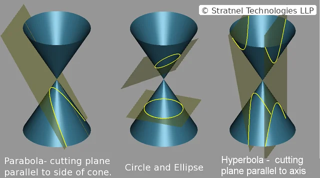
Conic sections — parabola, circle and ellipse, hyperbola. Source: Wikipedia, modified by Stratnel.
Each shape has distinct optical properties that suit different applications. A parabolic reflector, for example, generates parallel beams when the source sits at the focal point. We focus on parabolic reflectors — how to design and 3D print them. You can design and 3D print any conic section using the same approach.
From Equations to CAD
Modelling in Autodesk Fusion 360
© Stratnel Technologies LLP
Here is how to model a parabolic reflector in Autodesk Fusion 360 from first principles.
Andrew Sears from Autodesk Support describes this method in the Fusion 360 user forum. We expand on his steps below.
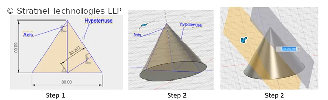
Start with the space your reflector must fit — defined by diameter D and height h. For this example, D=80 and h=30.
© Stratnel Technologies LLP
Construct a triangle with Base=D=80 and height=2h=60. Draw a line from the midpoint of the base, perpendicular to the hypotenuse. This is the offset distance — 33.282 in this example.
Revolve the area enclosed by the hypotenuse, the base, and the axis around the axis to generate a cone.
Generate a tangent plane. Move it by the offset distance (33.282) so it passes through the intersection of the offset line and the base, splitting the cone.
© Stratnel Technologies LLP
© Stratnel Technologies LLP
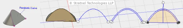
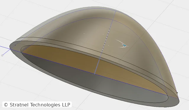
The splitting plane contains the parabola we need. Copy the parabolic curve and offset it outward by your required wall thickness — say 3 mm. Revolve the section to get the final reflector shell.
From CAD to Prototype
3D printing takes you from design validation through functional testing to small-batch production. As you iterate with your 3D printing partner, consider aesthetics, print orientation, and mounting arrangements.
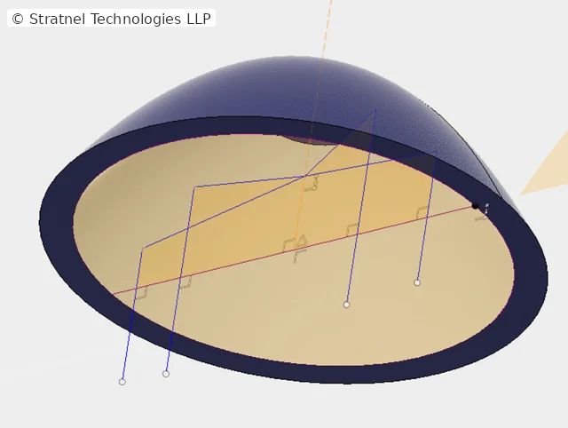
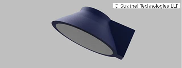
Here is an example of a parabolic reflector with an integrated mounting fixture.
© Stratnel Technologies LLP
Have a question or a perspective to add? Write to us below — we read every message, and may feature selected responses in a future post.