Using Fractals to Design Complex Shapes
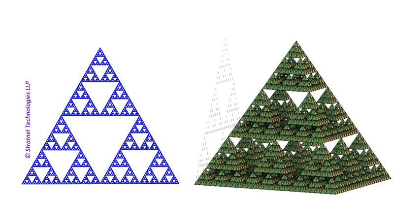
Fractals are geometric patterns that repeat at different scales. They exhibit the property of "self-similarity". Fractals appear complex in shape — but they are just iterations of simple geometries in a pattern. Consider an equilateral triangle: inscribe another equilateral triangle within it and continue doing this. You will end up with a Sierpinski's Triangle. This is a simple geometric fractal.
Fractals Intro
"A fractal is a never-ending pattern. Fractals are infinitely complex patterns that are self-similar across different scales. They are created by repeating a simple process over and over in an ongoing feedback loop. Driven by recursion, fractals are images of dynamic systems — the pictures of Chaos. Geometrically, they exist in between our familiar dimensions."
— fractalfoundation.org ↗Fractals appear all over nature from microscopic to cosmic scales. The arrangement of cells in living organisms and the distribution of stars both show fractal-like patterns. A simple example in daily life is the branching of trees, or lightning on a stormy day.
Origin of Fractals
The term fractal was first coined by Benoît Mandelbrot in 1975. It derives its origin from the Latin word fract, meaning broken or fragmented. Fractals are able to describe complexity in nature better than Euclidean geometry. According to James Gleick, "In the mind's eye, a fractal is a way of seeing infinity" — from Chaos (1987). Fractals are powerful tools. Various fields such as architecture, biology, weather modelling, astronomy, networking, and digital art all use fractals as a tool.
Application of Fractals
Fractals have been applied across several fields of human knowledge — including architecture, antenna design, and the mechanical cross-section of ropes. Fractals also appear in nature in many locations: the human lungs, the propagation of lightning, tree branches, and coastlines are all well-documented examples.
Exploiting Fractals in Engineering Design
3D printing can be used for creating complex shapes. Since geometry is not a limitation for additive manufacturing, fractal design helps in creating complex shapes to solve engineering problems. The discussion here focuses on design aspects only and does not cover the 3D printing process itself.
The principle of fractals can be exploited in engineering design in many ways. Some typical examples include weight reduction in structural members, compaction in antenna designs, heat transfer applications, and equalised fluid flow paths.
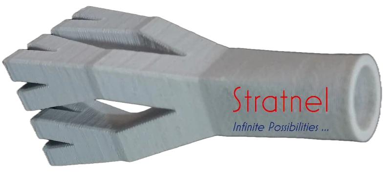
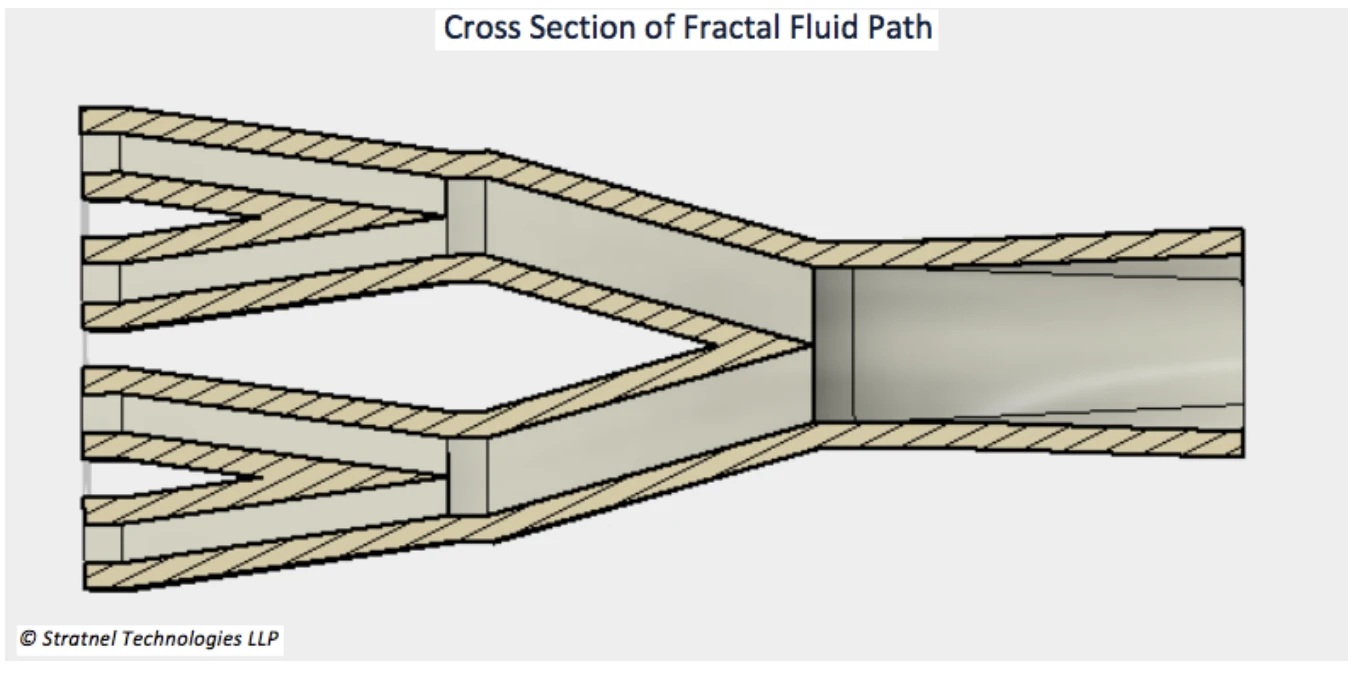
Here is an example of fractal fluid path creation. The objective is to divide fluid paths in an equalised pattern, keeping the overall flow area constant and minimising friction losses due to changes in flow length or direction.
Design Steps for Creating a Fractal Fluid Path
The following steps describe the main design sequence in Fusion 360, without some intermediate steps.
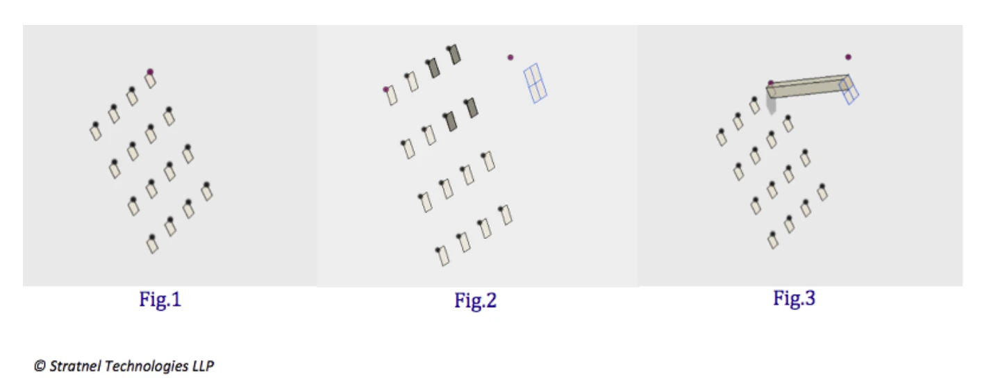
Create a pattern of 16 nos. 3 mm squares in a plane with a pitch of 10 mm between them in X and Y directions (Fig 1). Create another plane at a distance of 25 mm in the Z axis. Project the midpoint of the 4 shaded squares to the second plane and draw a square of 6 mm in the second plane with the projected point as the centre (Fig 2). This is an important step — the 6 mm square will have the same area as the sum of four 3 mm squares (4 × 3² = 6²). Dimensions can be adjusted to suit the application. Loft one of the corner 3 mm squares in the first plane to the corresponding quadrant of the 6 mm square in the second plane. This creates the first fluid passage (Fig 3). Wall thickness has not yet been added.
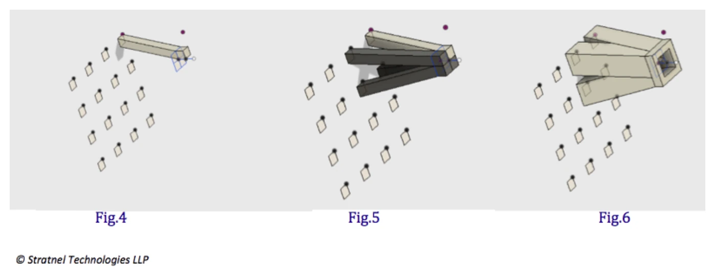
Extrude the top square after lofting by 3 mm. This is done to minimise the impact of direction changes by equalising after every step of the fractal division (Fig 4). Create a circular pattern around the centre axis to produce 4 identical bodies of fluid passage (Fig 5). Wall thickness is still not added. The next step is to combine the 4 bodies into a single body and shell outward with 2 mm wall thickness (Fig 6). We now have 4 flow paths of equal size, equal flow distance, and equal deflection angles — with wall thickness.
Create another plane at 25 mm from the top of the body created above and draw a square of 12 mm. As explained in step 1, this accounts for the same area as four 6 mm square flow areas (4 × 6² = 12²) (Fig 7). The 6 mm square passage is lofted to the corresponding quadrant of the 12 mm square (Fig 8). Again, the top surface is extruded by 3 mm.
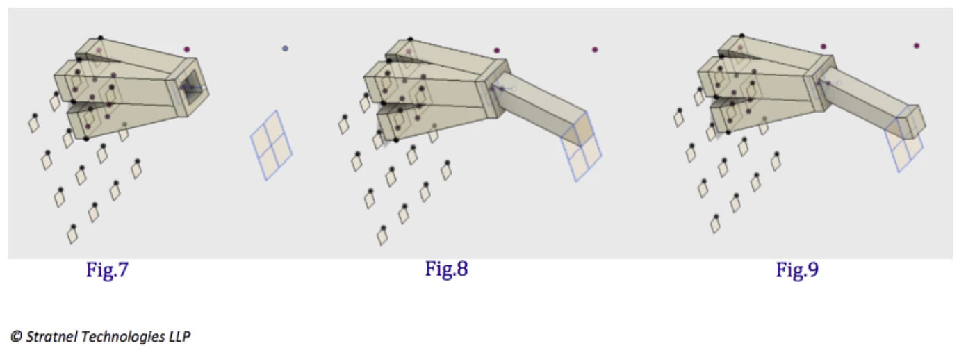
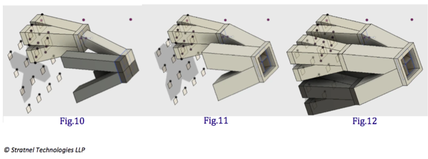
Similar to Fig 5, create a circular pattern to produce 4 bodies (Fig 10). These 4 bodies are combined and shelled outward with 2 mm wall thickness (Fig 11). The next step is to apply a circular pattern to the first set of combined body clusters in Fig 7, around the axis that passes through the centre of the 12 mm square.
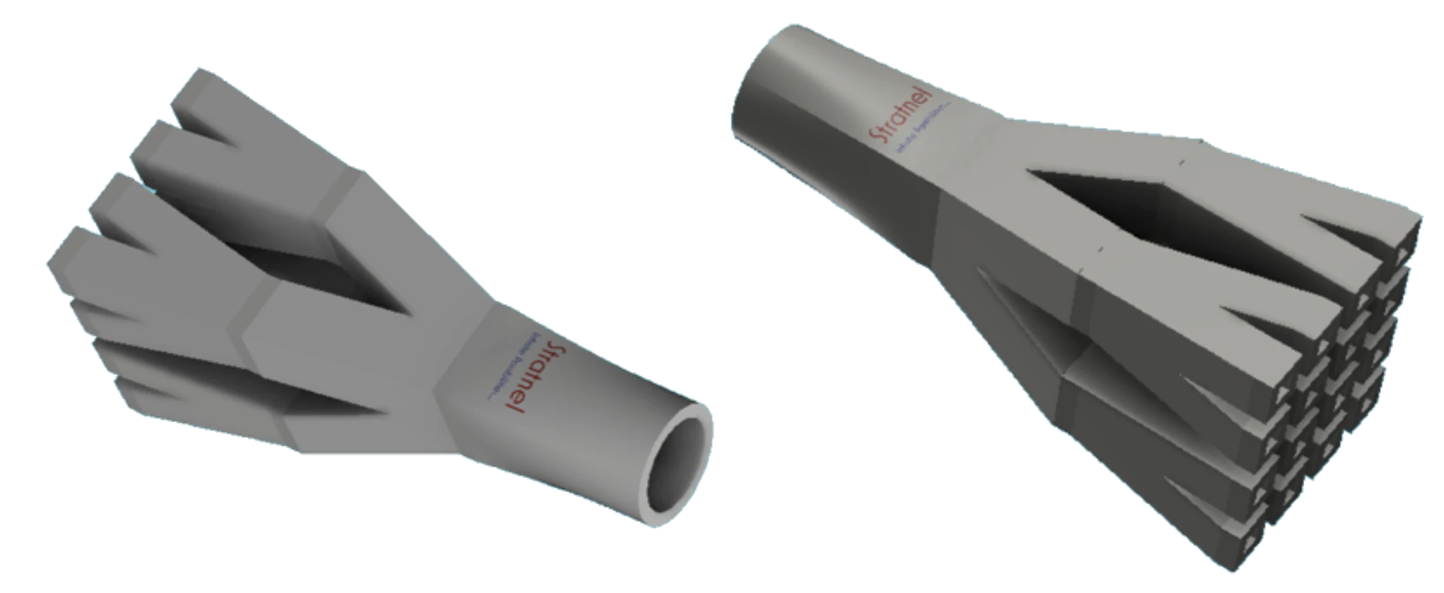
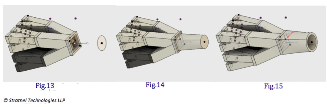
We are almost there. Add another body to convert the square 12 mm opening to a 13.543 mm diameter opening — again keeping the area constant (12 × 12 = π/4 × 13.543²). This is done to facilitate connection to round pipes. Create an offset plane by 30 mm and draw a circle of diameter 13.543 mm (Fig 13). Loft the 12 mm square to the 13.543 mm diameter circle (Fig 14). The final step is to shell the body outward by 2 mm and combine all bodies (Fig 15). Done.
Conclusion
These parts are well suited for 3D printing. One could also add other features such as threads or additional interface geometry. With shapes this complex, producing such a component through any other manufacturing process involves significant limitations — in design freedom, machining access, pattern-making, and overall cost. 3D printing is elegantly suited for manufacturing fractal-based designs.
Have a question or a perspective to add? Write to us below — we read every message, and may feature selected responses in a future post.